 English
 हिन्दी
Panel Method
Methodology
Panel methods are among the most versatile and powerful tools developed in the last three / four decades for the aerodynamic analysis of complex configurations like aircraft, space launch vehicles, automobiles, ships etc. In principle, panel methods solve Laplace equation. In panel methods, the calculations are confined to the configuration bounding surfaces thereby eliminating the need for volume mesh. This in turn makes it easy to obtain flow solutions about completely arbitrary configurations. In spite of their theoretical limitations and simplified approach, the predictions of panel methods have been found to agree well with experimental measurements over a large range of flow conditions. Even in cases where their predictions are not in good agreement with experimental measurements, they are still used in predicting the incremental effects of a proposed design change, for calculating static stability derivatives etc.
Major Milestones
The existing panel code in the division was modified for the analysis of propellers and helicopter rotors. The wake of a propeller has a strong influence on its aerodynamic characteristics. When the flow over a propeller is steady, the shape and orientation of its wake is assumed to be helical and axisymmetric. This approach is called quasi-unsteady analysis. The quasi-unsteady code was applied for the analysis of propellers.
The panel code of the division was coupled with an existing boundary layer code to simulate three-dimensional compressible flow. Results obtained from the coupled panel code were compared with experimental measurements for two-dimensional airfoil, wing and wing body. Very good comparisons between theory and measurements have been obtained.
The panel code of the division was modified to handle unsteady flows. Here the wake shape is unknown and is determined as part of the solution. The code has been applied to a pitching wing and two bladed helicopter rotor.
Highlights
NAL panel codes have served as a workhorse for the division:
- Steady (NAL Panel Method - NPM)
- Quasi-unsteady
- Unsteady (Unsteady Panel Method - UPM)
- Panel Method coupled with boundary layer code (NPM+BL3D)
The following are some of the configurations for which panel codes have been used extensively.
- Analysis of Light Transport Aircraft
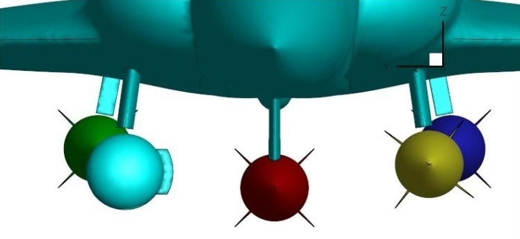
- Analysis of Marine, Aircraft and Octocopter propeller
- Analysis of Aerostats
- Analysis of Light Canard Research Aircraft
- Analysis of Sensor Optimised Airborne platform
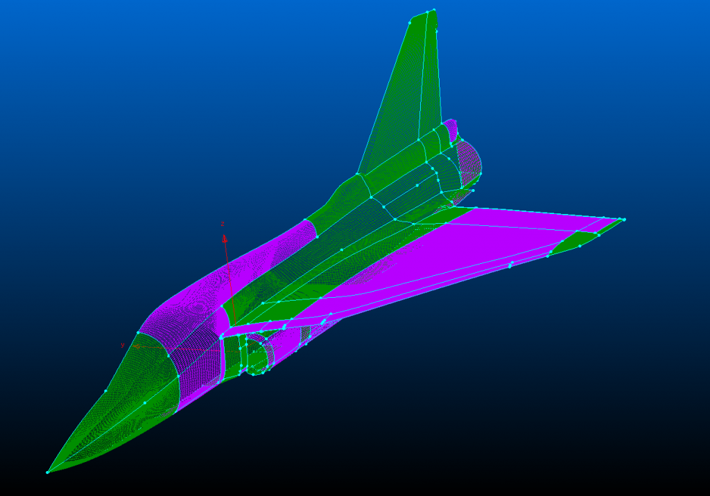
- Analysis Reusable Launch Vehicle
- Analysis of Wind Turbines Rotor Blades
- Analysis of Regional Transport Aircraft candidate configurations
Results
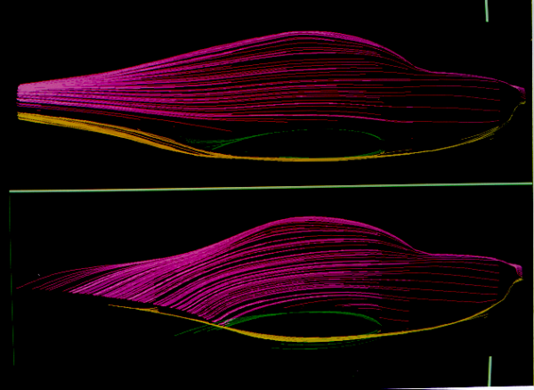
The figure shows the modification of aft fuselage to obtain a smooth flow of a two seat trainer aircraft.
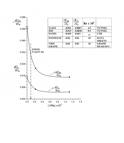
The figure shows the use of panel code in combination with experimental measurements for calculating the elevator effectiveness of SARAS.
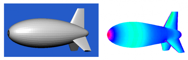
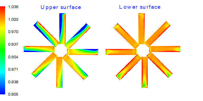
The figure shows the paneling and the pressure contour over an aerostat configuration.
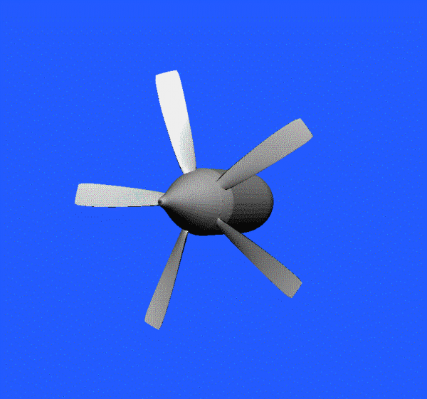
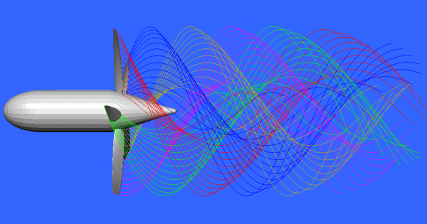
The figure shows the paneling of rotor blades and wake for a five bladed variable pitch propeller.
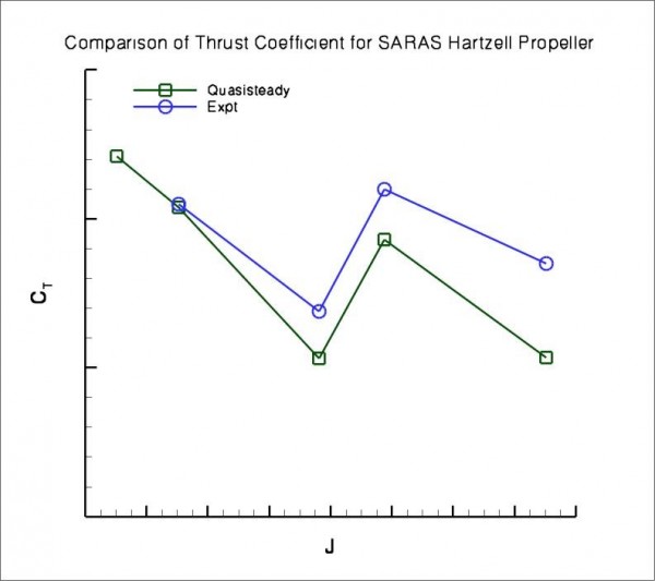
The figure shows the comparison between experimental measurement and quasi-unsteady analysis for a five bladed variable pitch propeller at different blade angle setting and advance ratios.
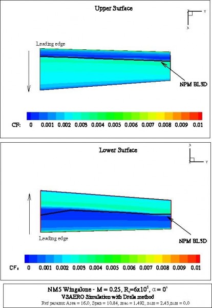
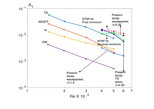
The figure shows the comparison of transition prediction by VSAero software and NAL panel code coupled with boundary layer code.
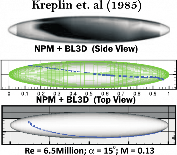
Figure shows the comparison of Transition Onset Prediction with Experiments. Reynolds Number = 6.5M, Alpha = 150 , Mach Number= 0.13.
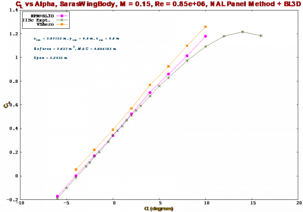
The figure shows the Lift Coefficient of Saras Wing Body, M= 0.15, Re= 0.85 M
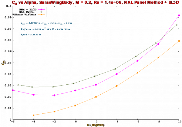
Figure shows the comparisons of NPM+BL3D computations with NAL wind tunnel experiments and VSAero computations for Saras Wing Body configuration for lower Mach number and Reynolds number.
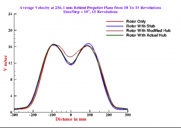
Figure shows the comparison for the four configurations with velocity average at 256.4 mm behind propeller plane. The computation was carried out using UPM.
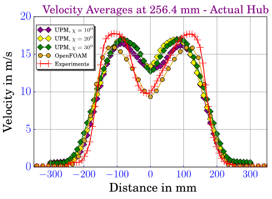
OpenFOAM results consisting of stream-wise velocity distribution at different sections are compared with experimental data and UPM results.
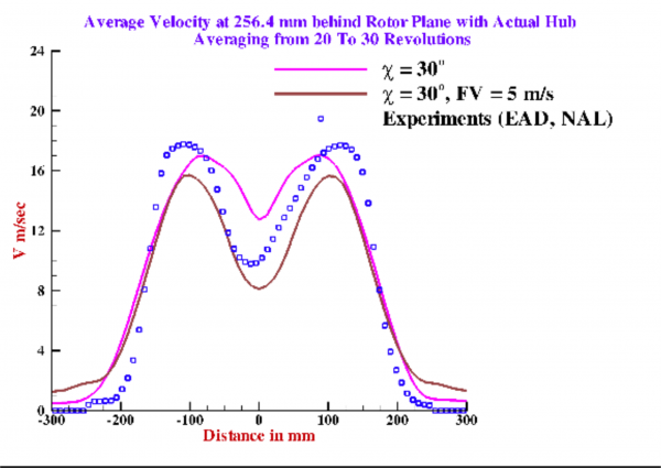
UPM computations were carried out using forward velocity as an additional input. The figure gives one such result.