 English
 हिन्दी
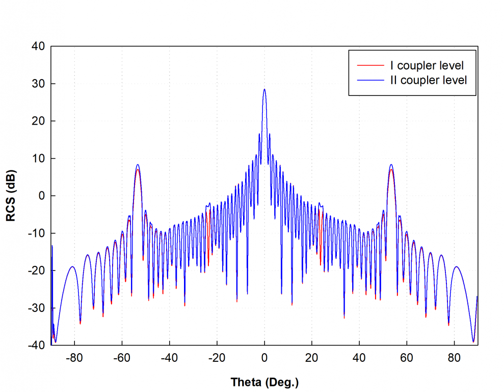
RCS Estimation and Control of Phased Arrays
Defense applications demand design of targets that exhibit the smallest possible RCS so as to be undetectable and untraceable for enemy radars by highly sensitive radars. For such a stealth or low RCS platform, it is not only required that phased antenna array has high performance (gain, sidelobe level, size, weight) but should also meet RCS requirements. Conversely, it is essential that any active/passive technique used to reduce RCS should not degrade the performance of antenna array.
An antenna mounted on the platform has a two-fold impact on the RCS of the platform. First, the antenna significantly disturbs the continuity of the surface (e.g., to mount an antenna array on the surface of an aircraft, holes are required to be drilled) and thus introduces more edges. Also, a well-designed antenna has the potential to absorb almost all the energy incident in its operating band. For example, a plate with an antenna installed has the scattering characteristics similar to that of a plate with a hole in it. These two factors collectively give rise to wide-angle scattering/ RCS. Secondly, the threat radar’s signal can penetrate into the feed of the antenna system and get reflected at internal mismatches and junctions. Even though these mismatches are small in the operating band, they may result in multiple scattering sources for a large array. These individual contributions may add constructively under some conditions. This scattering is dependent on the type of the feed and the components incorporated therein, and thus complicate the RCS prediction. The in-band antenna RCS consists of two antenna scattering modes- structural mode and antenna or radiation mode. Structural mode is generated by the currents induced on the antenna and the platform when the terminating load is equal to the complex conjugate of the antenna impedance and is primarily due to edge effects, viz. ground plane edge diffraction and mutual coupling changes near edges of the array. In contrast, the radiation mode is determined only by the radiation properties of the antenna and is proportional to the gain of the antenna in a given direction and the modified reflection coefficient.
For a well-designed antenna array, it is required that both the antenna and the structural mode scattering terms be small within its operating band. Usually, the antenna systems are chosen to have a higher gain accompanied with low scattering in order to ensure that they serve the requirements of both high performance as well as low RCS. Also, in usual practice, the antenna impedance is conjugate matched with its load impedance so as to enable maximum power transfer. Although terminating the antennas of a large array by matched receiver’s aid in eliminating the antenna scattering mode, it fails to yield lower value of RCS. This is because, for such a case, the scattered power from the antenna exceeds the absorbed power.
When an incident wave enters into the feed network of an in-band operational antenna, tracing of the signals through the feed requires the consideration of all the internal junctions and devices at which reflections occur. The sources of scattering in case of feed networks include antenna aperture, phase shifter, couplers, and terminating load. Other typical sources of scattering include devices that are not perfectly matched due to physical limitations (manufacturing and assembly errors, variation in the electrical properties of material, etc.), surface roughness (assembly tolerances, discontinuities, distortions, etc.), errors built into the antenna (e.g., quantization errors from sub-arraying), and edge effects. The scattering at various mismatches in the feed network continues as the signal travels deeper into the feed network. The vector sum of all these individual scattered fields that return to the aperture and reradiate will be equal to the total RCS. This analytical approach is used to derive the closed-form expression of array RCS. The software code is indigenously developed to perform simulation studies including parametric analysis.
Specifications:
- Software code development for RCS of phased arrays:
- Series feed network
- Parallel feed network
- Phased array configuration considered:
- Linear array
- Planar rectangular array (Figure 4)
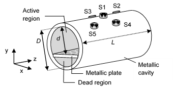
- Non-planar cylindrical array (Figure 5)
- Mutual coupling included.
Facilities where this technique is used: Defence labs
Major mile stones / results of this technique:
- Indigenously developed software codes
- Software copyrights
- CSIR-NAL Radar Cross-section (RCS) of Phased Array code (S/w Code Ref.: 6/CR/2012)
- CSIR-NAL Estimation of Backscattering Cross Section of Arbitrary Dipole Array Code (filed on 15.04.2013)
- Books
- Hema Singh, H. L. Sneha and R.M. Jha, Radar Cross Section of Dipole Phased Arrays with Parallel Feed Network. Springerbrief in Electrical and Computer Engineering-Computational Electromagnetics, ISBN: 978-981-287-783-3, 77 p., 2015.
- Hema Singh, R. Chandini and R.M. Jha, Parallel-Fed Planar Dipole Antenna Arrays for Low-observable Platforms. Springerbrief in Electrical and Computer Engineering-Computational Electromagnetics, ISBN: 978-981-287-813-7, 50 p., 2015.
- Hema Singh, H. L. Sneha and R.M. Jha, Scattering Cross Section of Unequal Length Dipole Arrays. Springerbrief in Electrical and Computer Engineering-Computational Electromagnetics, ISBN: 978-981-287-789-5, 58 p., 2015.
- Hema Singh, R. Chandini and R.M. Jha, RCS Estimation of Linear and Planar Dipole Phased Arrays: Approximate Model. Springerbrief in Electrical and Computer Engineering-Computational Electromagnetics, ISBN: 978-981-287-753-6, 47 p., 2015.
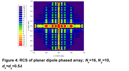
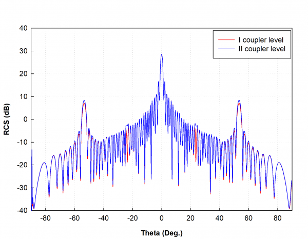

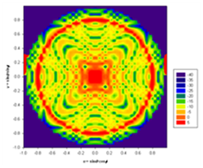
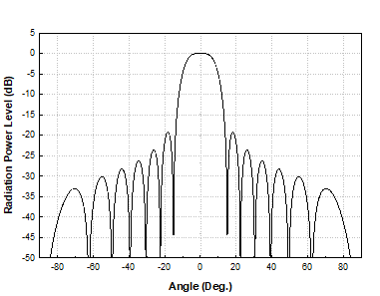
Figure 5: RCS of 16-element dipole phased array mounted over a conducting cylindrical surface