 English
 हिन्दी
EM Design and Performance Analysis of Planar Radomes
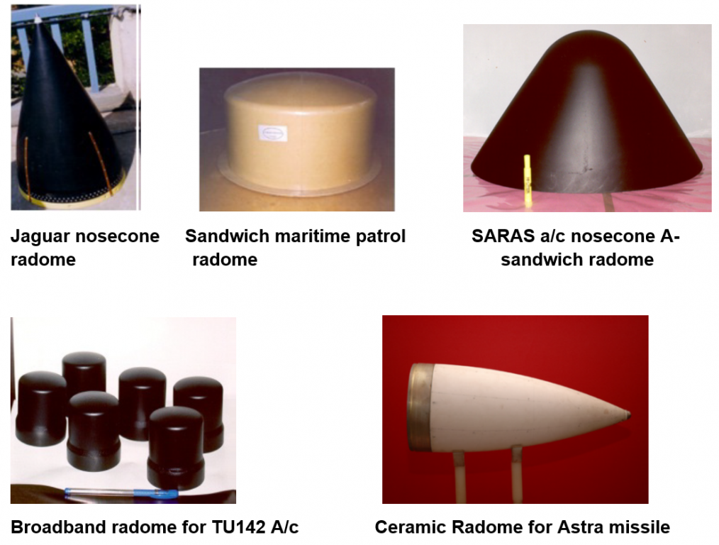
The antenna array system of aerospace and naval platforms are exposed to extreme environment such as rain, hailstorms, snow, wind, extreme temperatures etc. It is, therefore, imperative to make sure that these devices are well shielded without compromising their performance. A radome (acronym for radar dome) is such an electrically invisible structure that protects the antenna/radar. Ideally the shape, size, material and wall configuration of the radome makes it an absolutely transparent shield in electromagnetic spectrum. However, development of such radome can be a challenging task. Therefore, one has to pick the best combination of these parameters to allow the antenna-radome system to operate within the designated bandwidth with minimal electrical, spatial and economical losses. An efficient radome is expected to introduce gain loss of less than -1.0 dB.
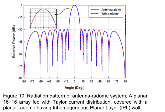
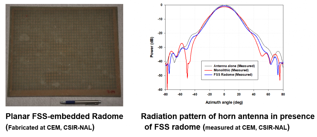
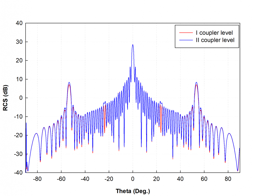
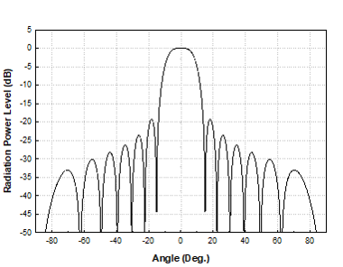
The antenna-radome performance analysis employs Geometrical Optics for deriving angle of incidence on the radome inner surface towards computation of reflection and transmission behavior of radome surface (Figure 10). Then an equivalent aperture (of antenna array) is hypothetically constructed (projected) on to the radome surface. The EM characteristics of this equivalent aperture are essentially that of the antenna-radome system. The far-field radiation pattern of the equivalent aperture is computed for both antenna alone and antenna with radome cases. Different types of wall configurations can be considered, viz. (i) monolithic wall, (ii) A-sandwich wall, (iii) C-sandwich wall, and (iv) graded dielectric wall. It is noted that the radome is assumed to be placed in the far-field of the antenna/array. If the radome is placed in the active region (near-field) of antenna, then geometrical optics would have to be replaced with some other numerical technique.
Specifications:
- Radome wall configuration: monolithic wall, A-sandwich wall, C-sandwich wall, and graded dielectric wall
- Aperture distribution: uniform, cosine, cosine-squared, Taylor, Dolph-Chebyshev
- Reflection/transmission coefficient, radiation pattern
- Planar and non-planar singly curved radome surface
- Different configuration of antenna array
Facilities where this technique is used:
- CSIR-NAL
- DRDO labs
- HAL
- BEL
- Private industries
Major mile stones / results of this technique:
- Indigenously developed software codes for EM propagation analysis of antenna-radome system
- EM material characterization for radome candidate material
- EM performance analysis in terms of transmission loss, boresight error