 English
 हिन्दी
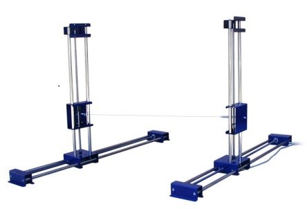
Design Center
A lot of literature are available on how to design a fixed wing aircraft. Most of the tools, like Advanced aircraft analysis, are based on the design theory as described by Roskam, Raymer etc. These traditional methodologies on fixed wing aircrafts have evolved over several decades but are not suitable for low Reynolds number flow regimes, typical for most small UAVs. As a consequence, these design methods result in aerodynamic and performance characteristics that can be skewed and misleading for small UAV applications.
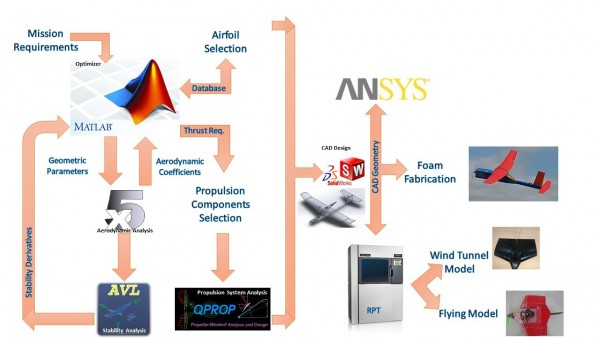
The design center at MAV unit has been established to cater to the design needs of fixed wing Mini and Micro UAVs and flapping wing MAVs. Apart from the low Reynolds number flow problems, the highly 3D flows due to low aspect ratio wing and propeller dominated flow over the wing makes the aerodynamic characterization a challenging one. The design team uses commercial codes like ANSYS-Fluent and open source tools like XFLR5 to obtain the aerodynamic characteristics and AVL, Tornado for obtaining the stability derivatives.
This facility houses high end work stations for the CAD and CAE needs, drawing release and rapid prototyping using 3D printing technology for a quick assessment of the design. This machine can also be used for making wind tunnel models as well as flight worthy models if designed properly. The foam cutting machine enables the unit to develop the flight model in no time and less cost. This lab houses a software tools and equipment that allow researchers to quickly build and modify MAVs. The lab even has a laser cutter with the ability to cut soft materials like Balsa wood, Cardboard, Acrylic etc.
Objectives
- Design, analysis and development of fixed and flapping wing MAVs.
- Implementation of open source design tools for conceptual and detailed design.
- High fidelity computational analysis.
- Advanced Prototype fabrication.
Specifications
RPT (Rapid Prototyping)
The fused deposition modeling (FDM) process constructs three-dimensional objects from 3D CAD data. The process starts with importing the STL file of the model into a pre-processing software, which is then oriented and mathematically slices into horizontal layers varying from ± 0.127 – 0.254 mm thickness. After reviewing the path data and generating the tool path, the data is sent to the FDM machine.
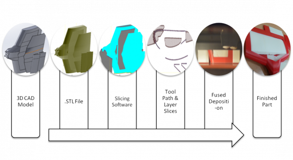
Figure 1:FDM process
|
Machine Specification |
|
|
Type |
Fused Deposition Modelling (FDM) |
|
Materials used |
ABS-M30 (Black, Blue, Grey, Red and White) and Nylon( Phase 2) |
|
Build envelope |
355 x 254 x 254mm |
|
Layer thickness |
From 0.127 mm to 0.330 mm |
|
Support structure |
Soluble SR 30 |
|
Achievable accuracy |
±0.127 mm or ±0.0015 mm/mm |
|
Power requirements |
230 VAC, 50/60 Hz, 3 phase, 16 A/Phase |
|
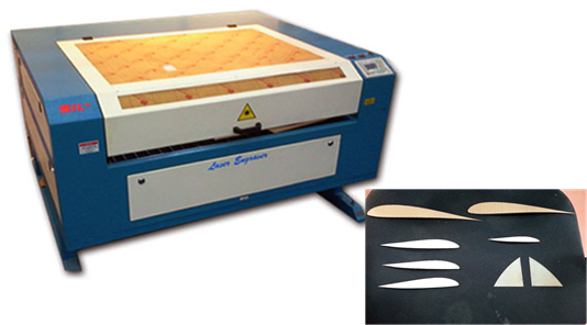
Figure 2: Laser Cutting Machine
|
||
|
Laser type |
Co2 DC Glass Laser Tube |
|
|
Wave Length |
10.6 um |
|
|
Supply Voltage |
AC 220 V + 10% |
|
|
Re-positioning Accuracy |
0.1 mm |
|
|
Cutting Speed |
0~30000 mm / min |
|
|
Engraving Speed |
0~64000 mm / min |
|
|
Cooling Method |
Water Cooled |
|
|
Work Environment |
Temp: 0 c ~ 45 c. Humidity: 5% ~ 95% |
|
|
Acceleration Speed |
1 G |
|
|
Working Area |
600×400 mm |
|
|
Graphic File support |
PLT, CDR, AI, DWG, DXF, DST, BMP, JPEG, TIFF, GIF, PCX, etc. |
|

|
|

Figure 3: Foam Cutting Machine |
|
|
Effective horizontal travel |
380 mm |
|
|
Effective vertical travel |
225 mm |
|
|
Axis |
4 Independent Axis (Will Cut Tapered Wings) |
|
|
Electronics |
4 Axis Pulse and Direction on Printer Port |
|
|
Motors |
NEMA23 2.8A 3.3V |
|
|
Power |
110 V 200W |
|
|
Cutting speed |
Software Dependent – up to 20”/min |
|
|
Resolution |
4800 Steps per Inch |
|

Techniques applied in this facility
- MDO (Multidisciplinary Design Optimization)
- CAD Modelling (SolidWorks)
- Computational Analysis (ANSYS Fluent)