 English
 हिन्दी
Combustion and Gas Dynamics Laboratory
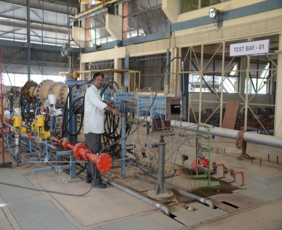
Combustion laboratory is involved in the design, development, testing and analysis of gas turbine combustors for small gas turbine engines. In this facility performance parameters like combustion efficiency, total pressure loss, pattern factor and emission levels of combustor can be evaluated up to maximum pressure of 8 bar. Combustor configurations like can-combustor, reverse flow combustor, straight flow combustor and slinger combustor can be tested in the facility. Figure 1 shows the fully instrumented combustor assembled in the test facility.
Inlet pressure conditions : 0.5 to 8 bar
Mass flow rate : 0.5 to 6 kg/s
Exit temperature range : 600 – 1450 K
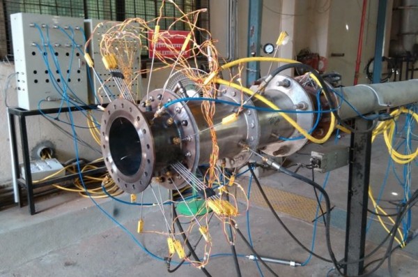
A fully automated test and control system is designed and developed for testing straight flow annular combustor (mass flow rate – 1.75 kg/s). This system (Figure 1) has capacity to measure 50 temperatures, 10 pressures and 5 fuel flow conditions. The mass flow rate of fuel and air can be accurately controlled to simulate different operating conditions. The performance parameters are derived from the measured parameters like, temperature, pressure and mass flow rate of fuel and air streams.
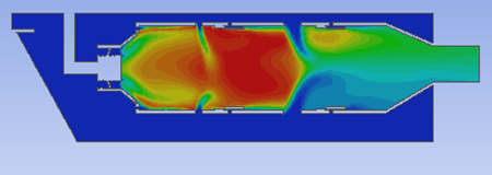
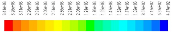
In the design stage of gas turbine combustor CFD is used to optimize the combustion chamber performance parameters such as mass flow distribution, temperature field and velocity field, figure 2 shows mid-plane temperature contour of gas turbine combustor. Results of cold flow CFD simulations (with K-e or RSM turbulence model) are used to characterize the mass flow distribution and total pressure loss. Results of hot flow CFD simulations (with Mixture fraction and species transport approach to simulate combustion process) with DPM technique are used to characterize the temperature field in combustor and temperature profile at exit of the combustor. VOF and DPM techniques are used to simulate the two phase flow field associated with atomization process of simplex atomizer and liquid jet in cross flow air stream.
Atomization and sprays
This laboratory is also involved in studying atomization and sprays. Small scale – simplex atomizers are developed for various fuel flow rate conditions with improved atomization capacity. While characterizing the atomizer, performance parameters like spray cone angle, Sauter mean diameter and coefficient of discharge are experimentally evaluated. Malvern spray analyzer shown in figure 3.a is used to measure Sauter mean diameter of spray at different operating conditions. Figure 3.b shows various stages of spray with respect to operating conditions of different atomizer configurations. Using the experimental data of simplex atomizers at various operating conditions better empirical correlations are developed.
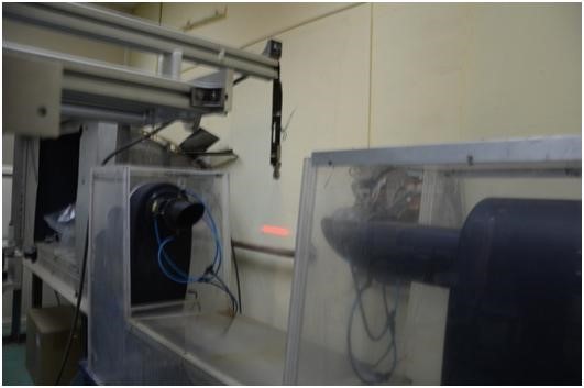
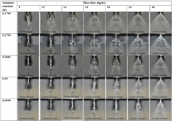
Figure 3.a Malvern spray analyzer | Figure 3.b. Different stages of spray of various atomizer configurations