 English
 हिन्दी
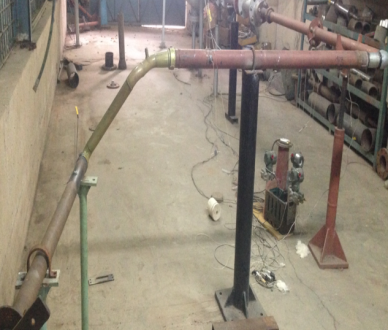
Closed circuit Centrifugal Compressor Test Rig Facility
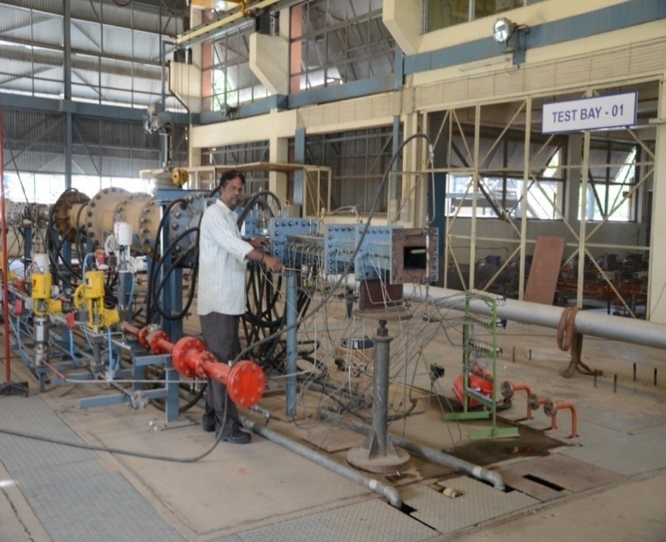
FACILITY 1: Closed circuit Centrifugal Compressor Test Rig Facility
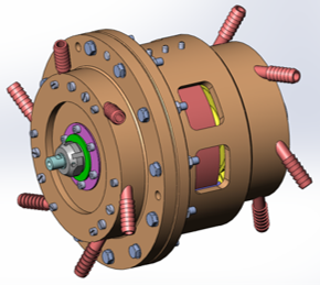
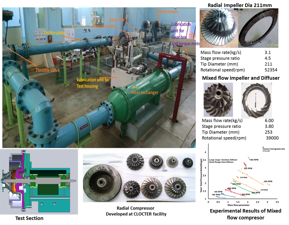
The Closed Circuit Centrifugal Compressor Test Rig (CLOCTER) facility is established at Propulsion Division to predict the detailed experimental performance of the centrifugal compressor and mixed flow compressor stages. The tests are carried out in the simulated conditions, such that corrected mass flow parameter and the corrected speed are matched with the operating points / design point.
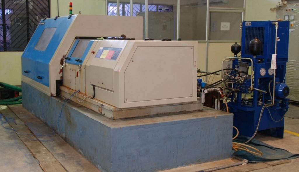
The main loop has twin DC motor of 375 kW (187.5kW each) as a prime mover, step up gear box (1: 20), torque meter to measure (speed, Torque and power), test section, heat exchanger, 10” motorised gate valve, orifice flow meter and 10” line. Two separate lubrication systems are provided for gear box and test section, which supplies lubrication oil at 150 lpm. The test section has special combination bearing to take care of the radial and thrust force generated by the centrifugal compressor. The rig is augmented with a cooling tower system which supplies DM water for the heat exchangers (Main Loop and lubrication units).
The rig is capable to test up to tip speed of 550m/s, impeller diameter of 525mm, different working mediums, Reynolds numbers and Mach numbers.
Specifications
Speed : 60,000 rpm (max)
Power : 375 kW, Thyristor controlled twin DC motor.
Test component size : diameter 525 mm (max)
Mass flow rate : 6 kg/s (max)
Impeller tip speed : up to 550 m/s
Pressure ratios : up to 6
Working medium : Air, Freon-12, R134A & Ammonia
Major clients of this facility
GTRE Bangalore, ADA- Bangalore, HAL –AERDC, GE-Oil and Gas, KPCL Pune
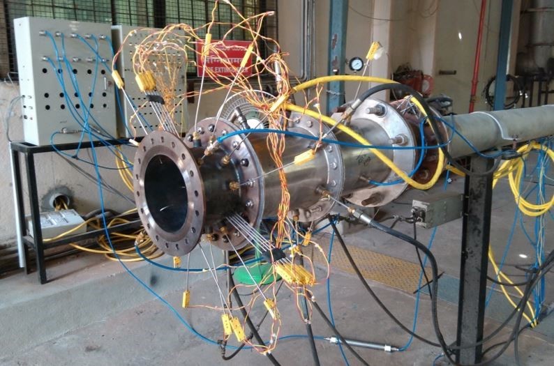
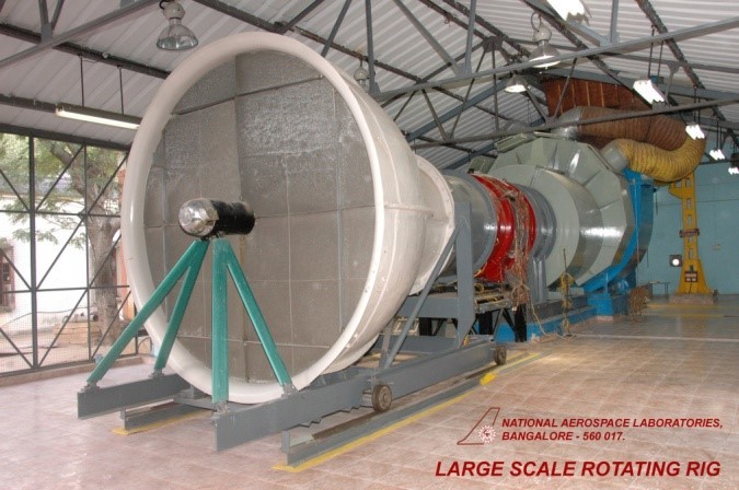
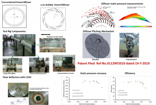
FACILITY 2: Annular Cascade Tunnel for radial diffuser characterization
An annular cascade Tunnel was designed and established in the year 2011 to carry out the performance prediction of the radial and mixed flow stators. In the test rig, specially designed swirlers are used to simulate the impeller exit flow angle and Mach number. The rig can be used to characterize and optimize diffusers.
Specifications
Mass flow rate : 1 kg/s (max)
Inlet pressure : 3 bar
Inlet Temperature : 300K
Max Mach Number : 0.8
Working medium : Air
Major clients of this facility
GTRE Bangalore, HAL –AERDC, GE-Oil and Gas, KPCL Pune
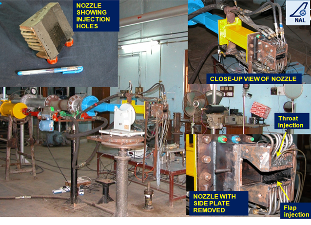
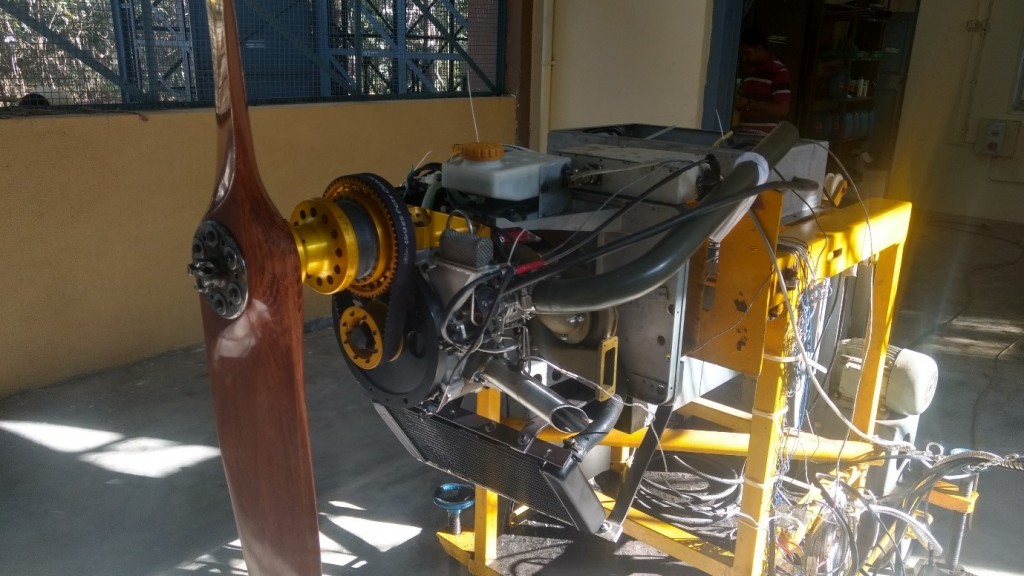
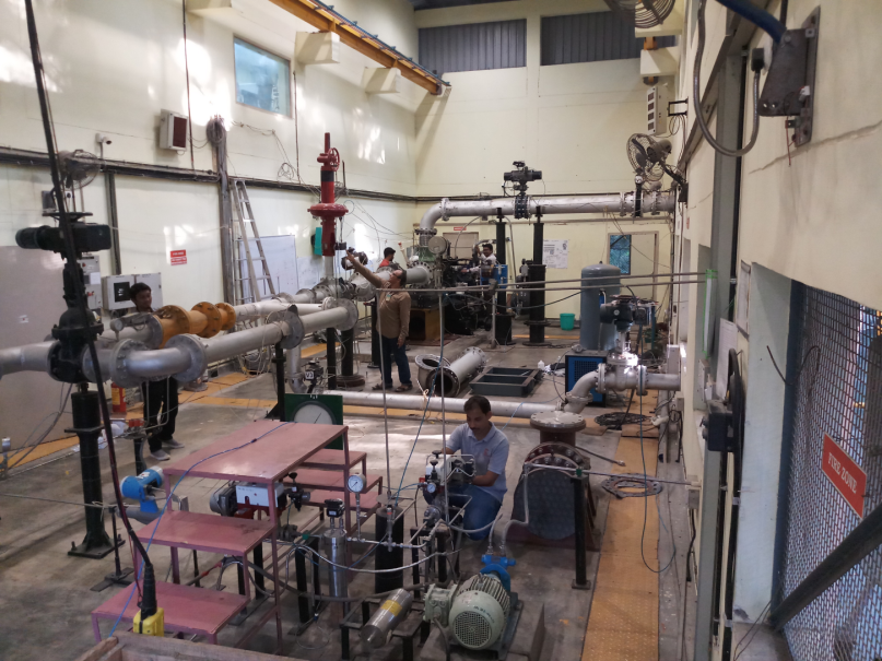
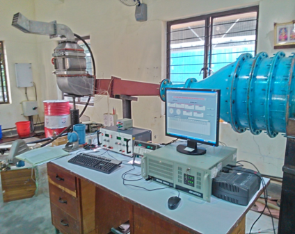
FACILITY 3: Experimental performance of Heat exchanger and LRU’s
A tunnel test rig was designed to simulate the inlet condition of the pre-cooler jet pump heat exchanger and LRU’s of aircraft system to predict the performance.
Specifications
Mass flow rate: 1.1 kg/s
Inlet pressure: 6 bar
Inlet Temperature: 600K
Working medium: Air
Major clients of this facility
ADA – Bangalore and HAL – AERDC