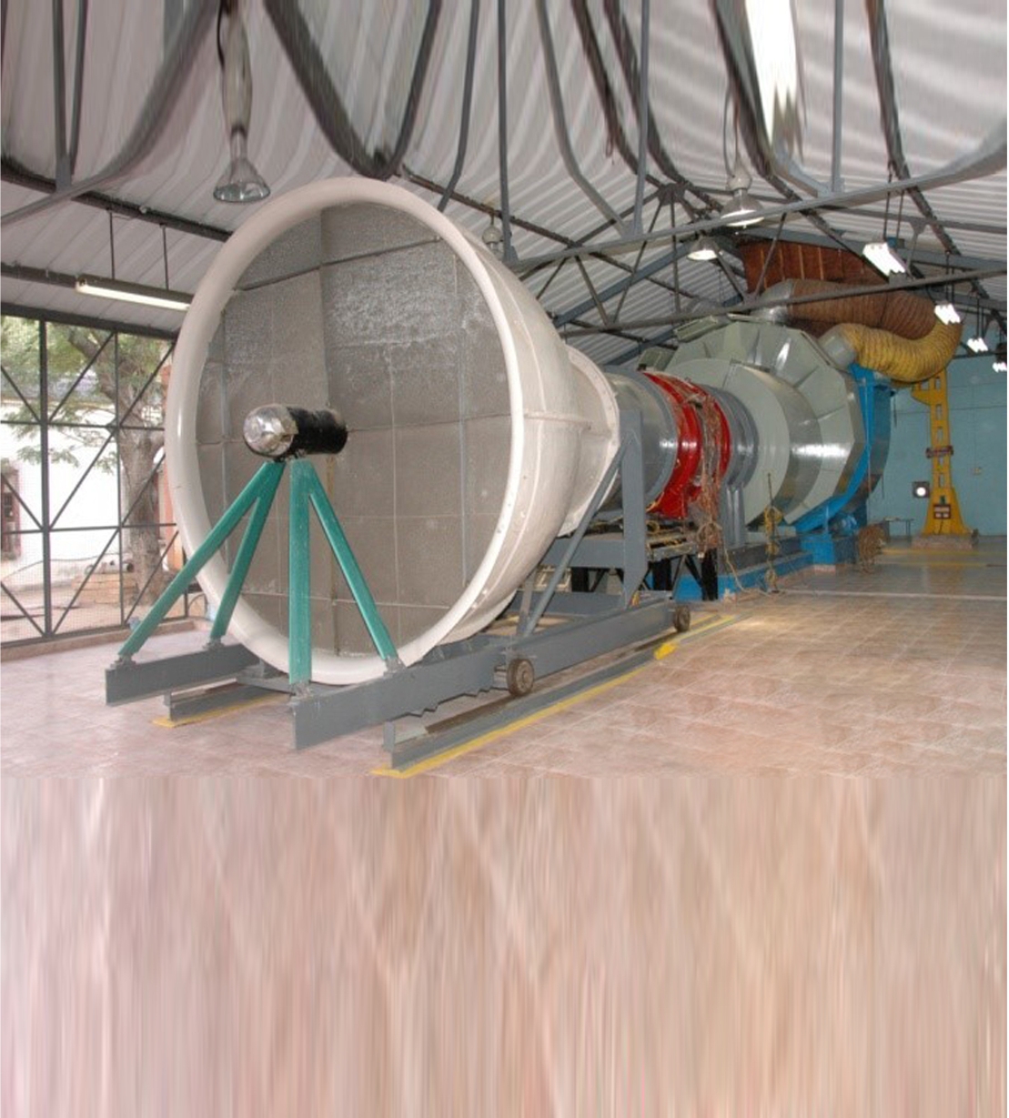
LARGE SCALE ROTATING RIG
The Large Scale Rotating Rig (LSRR) is a low speed, open circuit, suck-down type of facility. It is a specially designed experimental rig to carryout basic research and innovation in the field of turbo machinery at low speeds and room temperature. The rig can be used to test a turbine stage or a compressor stage with appropriate hardware changes. The rig incorporates a 12’ diameter circular bell mouth with honeycombs and screens for minimizing flow eddies, followed by an annular model section currently carrying a turbine stage. A dumb diffuser is provided downstream of the model section for pressure recovery. A 200 hp DC motor is mounted inside the dumb diffuser to drive the turbine rotor which can run at various speeds up to a maximum of 950 RPM. This motor also functions as a generator/electrical dynamometer to absorb the power developed by the turbine while the rig is running and regulates the speed of the rotor. At the end of the diffuser a pneumatically operated vortex valve is provided to control the mass flow through the model section.The rig also incorporates a centrifugal blower mounted at the exit of the dumb diffuser to suck air through the model section.The blower is driven by a 600 hp AC motor that can run at a constant speed of 700 RPM. Mechanical instrumentation for measuring aerodynamic quantities are readily available in the rig which includes 5-hole pressure probes, 3-hole cobra probes, static pressure tappings at various locations on the vane / blade surfaces and platforms.One 5-hole probe integrated with a cobra probe is mounted at the vane exit on the casing and another such set is mounted at the blade exit on the rotor disc.The vane exit probe combination is used to measure steady state total pressure, static pressure / flow velocity and flow direction in the circumferential plane at any chosen radial location in the stationary frame.The blade exit probe combination is used to make similar measurements at the rotor blade exit plane in the rotating frame.The rotor casing is instrumented with high response transducers for unsteady pressure measurements.
Stationary Frame Measurements
- Vane surface pressure distribution measurements using ZOC pressure scanners.
- External probe traverse system for Vane exit flow measurements
Rotating Frame measurements
- Internal probe traverse system for Blade exit flow measurements
- Calibration of Internal Pressure transducers in rotation
- Blade surface pressure distribution measurements using 48 port Scanivalve mechanical multiplexer.