 English
 हिन्दी
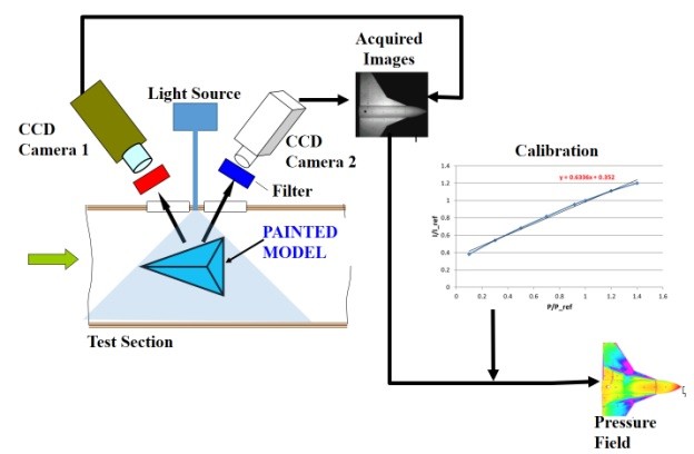
Pressure sensitive paint
Surface pressure measurements are of great importance for basic fluid dynamics experiments, studying specific flow phenomena, and validating computational fluid dynamics codes. The surface pressure measurements are routinely carried out to investigate and measure aerodynamic parameters and provide inputs to structural designers, the data that is crucial during initial design cycle. The traditional method of measuring surface pressure distribution involves instrumenting the model with several pressure taps (hundreds or thousands depending on the size of the model and complexity of measurement) drilled into the aerodynamic model surface and connected via tubing to multiplexed electronic pressure transducers. The data from these pressure taps are used to map the lift needed to properly engineer support structure and other features of the model. However, this method inherently comes with several disadvantages:
D It is both expensive and time consuming.
D Furthermore, measurements are made at discrete locations and it is generally impossible to install pressure taps at thin edges and sharp corners of the models where these areas are the areas of most interest.
The method of drilling holes into the surface of the model makes the model weak and therefore, puts a limitation of the dynamic loads the model can take and therefore, on the testing Reynolds numbers. A new method of obtaining surface pressures, without incrementing the model, based on luminescence technique, received considerable attention of aerodynamicists due to its tremendous potential and advantages.
Pressure sensitive paint is an optical method florescence property of certain compounds to obtain the pressures on a wind tunnel model surface without incrementing it. The surface is coated with a paint containing luminophore (dye) molecules and illuminated with light source capable of exciting these luminophores. As a result they fluoresce and emit light of a longer wavelength than that of the excitation wavelength due to internal transition before excitation. The deactivation process takes two paths : 1) deactivation through thermal collisions 2) Some luminophores are deactivated through collision with oxygen molecules, the process known as oxygen quenching (i.e the emitted luminescence is absorbed by oxygen molecules, hence a loss of emitted intensity). As the relative contents of constituents of air contributing to pressure are constant, the effect gives an indication of the air pressure above the surface. Hence the lower the pressure, the higher emitted light. The theory shows that the pressure is proportional to the inverse of the emitted light intensity
This phenomena can be incorporated into an optical pressure measurement system. As illustrated in Figure , the basic concept is fairly simple. An oxygen quenched photoluminescent compound is dispersed in an oxygen permeable binder to form a pressure sensitive paint, PSP. This paint is applied to an aircraft model and excited with a proper light source. The light source must be filtered that it emits no light in the luminescence band. A high resolution photodetector (Camera) views the model through a filter that removes all light except that emitted by the paint. The distribution of pressure over the model is computed from the measured distribution of light intensity (calibration); i.e. the brighter a point in the image, the lower the pressure.
The technique has the following distinct advantages.
- Apart from eliminating pressure taps, the PSPs provide surface pressure distribution with very high spatial resolution (constrained only by the lense-CCD camera arrangement and the resolution of the cameras).
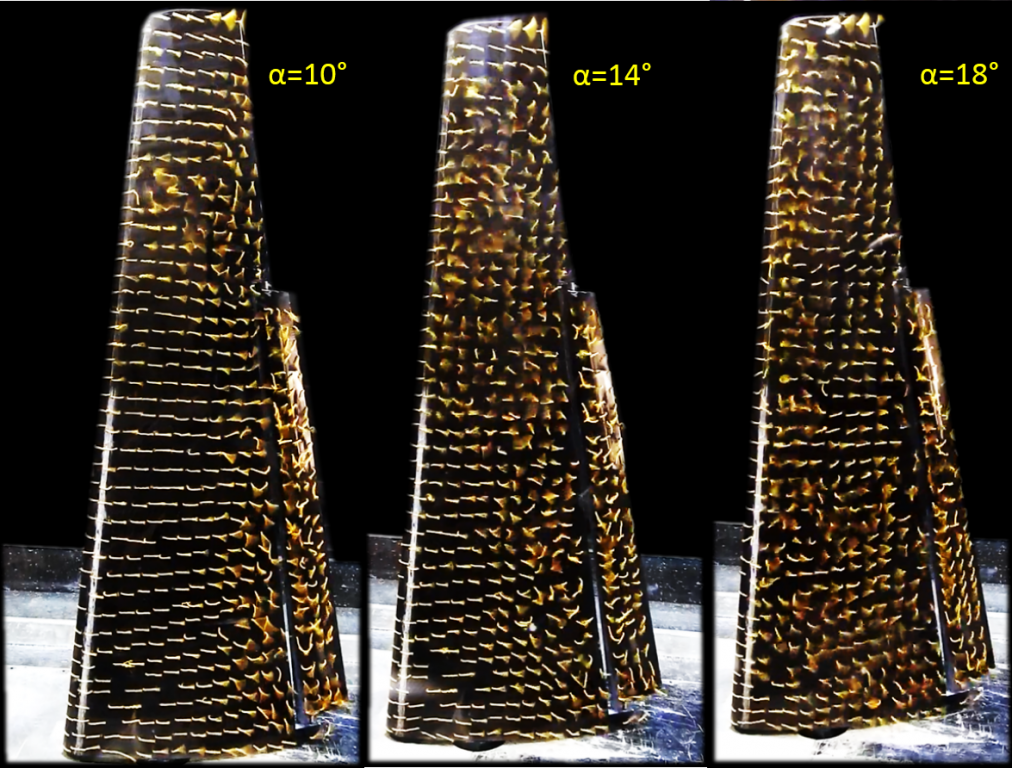
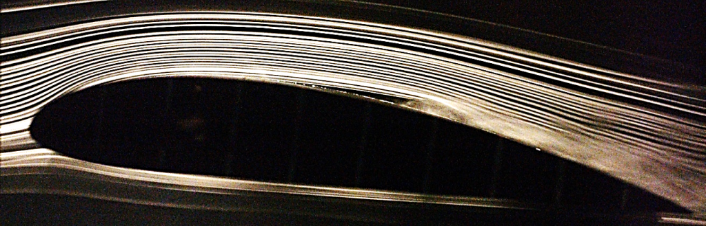
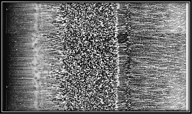
- The technique also provides flow visualisation. One can observe flow features such as shock locations, boundary layer separation, and reattachments .
- The PSP technique is much less time demanding and is cost effective.
Schematic of PSP setup
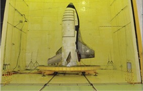
PSP system in EAD
The intensity based PSP system at NAL consists of an UV-flash lamp, two scientific grade CCD cameras, the calibration equipment and an in-house developed resection based image processing software. Excitation of the PSP on the model is provided by a xenon flash lamp emitting UV light in the range of about 405 nm wavelength. Optimum distribution of illumination on the entire model surface is obtained by using four illuminator heads connected to the lamp system by four 15 m long optical fibre cables. The paint emission data is acquired by two air-cooled scientific grade 12-bit CCD slow scan cameras with resolution of 1280 x 1024 pixels. The image acquisition is made by a PC based data acquisition system based on two separate PCI-cards. The camera and illumination are triggered and controlled by PC based software. The image integration time is typically 9-12 seconds so as to have a large pixel fill ratio in the CCD array (to have large signal to noise ratio). The sequence of measurement involves acquisition of images from the two cameras (the pressure sensitive and the intensity sensitive): a) ambient pressure and temperature b) dark images c) pre-run wind-off images d) wind-on images and e) post-run wind-off images. Camera objectives of 8 mm and 12 mm focal length are ideally suited for imaging models in NAL tunnels providing maximum spatial resolution of PSP images.
PSP Data Processing steps
The PSP sensor on the models and the calibration surface are prepared at the same time. It is typical to instrument the model with a few static pressure ports in order to compare the PSP data with that of conventional port data. Measurement uncertainty <±0.02 in Cp has been obtained in our tunnels so far. The temperature drop experienced in NAL blowdown tunnels are in the range of 3oC during PSP acquisition durations of 9s and the effect of this drop (being lesser on the model surface) has been proved negligible.
Specifications
Pressure range: 100 mbar to 2 bar
Uncertainty: <±0.02 in Cp
Spatial resolution: 0.1 mm
Major mile stones / results of this technique
Pressure field image of typical combat aircraft
Comparison between ESP and PSP measurements on Aircraft wing body model