 English
 हिन्दी
Particle Image Velocimetry
1.Particle Image Velocimetry
One of the serious limitations of the LDV technique is that it is a pointwise measurement. This in addition to the increased time required to map the plane of a given flow field, also implies the inability to carry out spatial correlations of data recorded simultaneously at different spatial locations. This is imperative for resolving non-stationary flow structures. The Particle Image Velocimetry (PIV) technique is one answer to the challenge. The measurement of the velocity field using PIV is based on the ability to accurately record and measure the positions of small tracers suspended in the flow as a function of time35. The velocity is then deduced as the displacement divided by the time interval (Figure 16). The degree of closeness of this estimate to the true velocity depends on how accurate the particle displacement, is measured and on the time interval. A too short interval results in an undetectable displacement whereas a too long interval averages out the fast fluctuating components.
Thus, for an accurate representation of the flow velocity, the time interval must be of the order of a relevant flow time scale. Typically, this scale is the ratio between the flow length scale, e.g., the Taylor macroscale, and the maximum velocity in the field. It is important to realize that once the “averaging” time has been determined, the flow scales that are represented by the recorded images have been fixed, and information contained in time scales beyond the time interval are forever lost.
![]()
1.1.Two-component Particle Image Velocimetry
![Fig 3. Phase-averaged velocity field at zero degrees (From [3])](/sites/default/files/inline-images/Fig%203.%20Phase-averaged%20velocity%20field%20at%20zero%20degrees%20%28From%20%5B3%5D%29.png)
Fig 3. Phase-averaged velocity field at zero degrees (From [3])
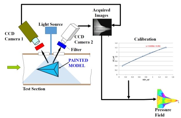
![Fig 2. Schematic of a typical 2D PIV setup (From [2])](/sites/default/files/inline-images/Fig%202.%20Schematic%20of%20a%20typical%202D%20PIV%20setup%20%28From%20%5B2%5D%29.png)
Fig 2. Schematic of a typical 2D PIV setup (From [2])
light source (usually a double-head pulsed laser system), and the light scattered by them is recorded onto two subsequent image frames by a digital imaging device, typically a CCD camera. Correlation then yields the displacement of particles at each “grid point” on the image. Figure 2 shows a cartoon of the process. Two dimensional PIV (2DPIV) enables the capturing of instantaneous and mean flow fields in a 2D plane of the flow illuminated by a laser. The velocity vector field so obtained can also be used to compute the vorticity fields. PIV has been applied to study subsonic and supersonic flows, as well as flows at extremely low speeds and water flows.
Application of 2D PIV can either be in an ensemble averaged form or be time-resolved (wherein the framing is faster than the flow time scales) or phase locked (i.e., capture the different phases of a periodic flow). Figure 3 which shows the mean velocity and vorticity field in the mid-plane of the vortex shedding behind a circular cylinder at low speed, demonstrates the latter. The trigger for the phase locking was achieved by means of a signal from a hot-wire probe, placed in the flow behind the cylinder. The reversed flow is indicated by red vectors. The presence of the shed vortex on the lower side of the cylinder, and vortex being formed on the top are seen in the velocity and vorticity maps. The complex nature of the velocity field including reversed flow zone may be observed, showing the asymmetric nature of the shedding from the upper and lower surfaces.
The 2D PIV technique is now routinely applied in major wind tunnels globally with specialized adaptation developed to cater for the special requirements of each facility.
1.1.Three Component Particle Image Velocimetry
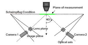
Out-of-plane motion (i.e., three-dimensional motion) of seeding particles which move out of the laser sheet plane is a severe limitation of 2D PIV in application to fluid flow. The reason for this limitation is that out-of-plane motion results in correlation loss. However, the fact that there is a detectable effect due the out-of-plane component of motion opens the possibility for its measurement. The strategy consists of a stereoscopic technique capable of measuring three velocity components in selected planes of a flow field. The technique is flexible enough and especially adapted for use in Wind Tunnel Applications. In this method, the images of particles suspended in the flow are recorded using a stereoscopic set-up. The stereo-pair views of the “flow-plane” are acquired in digital form via a high-resolution electronic imager. Each stereo-pair view is processed using a high-resolution correlation algorithm yielding velocity maps that are combined to reconstruct the three-dimensional velocity field. Due to the off-axis viewing of the laser plane, a special lens mount called a Schiemplug mount (Figure 4) is used to avoid de-focus of the plane on to the sensor array.
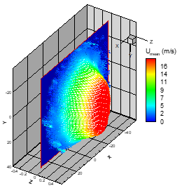
Figure 5 shows the three-component field at the exit plane of an elliptic nozzle.
Figure 6 demonstrates the capabilities of StereoPIV in educing flow physics. The figure shows the three-component velocity field over a Micro Aerial Vehicle at large incidence.
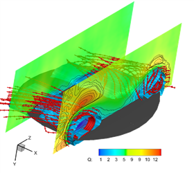
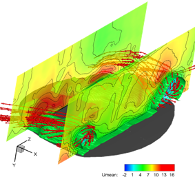
The iso-surfaces of the vortex cores are also plotted as are the stream traces through the vortex cores. In the propeller off condition, the port side has higher magnitude of positive vertical velocity component in the tip; lower magnitude of negative vertical velocity component in the inboard region and lower magnitude of tangential velocity component near the surface compared to the starboard side. During prop-on, both tangential and vertical components are equal in magnitude on both sides of the wing centerline and the magnitude of the negative vertical velocity increased in the inboard region which brings the flow towards the wing planform and causes the attached flow.
Bibliography
- L. Lourenco, A. Krothapalli, and C. Smith, Particle Image Velocimetry, 1989, “Advances in Fluid Mechanics Measurements”, Ed: M. Gad-el-Hak, Springer-Verlag, pp.128-199.
- www.dantecdynamics.com
- Venkatakrishnan L Madhavan, KT, Viswanath, PR (2006) Phase-Averaged 2D PIV Measurements on a cylinder with Forward Splitter Plate. Discussion Meeting on Flow Control and Diagnostics, 19-22 Feb 2006, Coorg, India.
- Venkatakrishnan L (2003) Some Observations on the Axis-Switching Elliptic Jet”. Sym Adv Flu Mech, July 24-25, 2003, Bangalore, India.
- Sudhakar, S., Chandan Kumar, A., Venkatakrishnan, L., (2017)” Influence of propeller slipstream on vortex flow field over a typical micro air vehicle”, Aeronautical Journal, 121 (1235), pp. 95-113.